
Coach Circuit Schematics
Master and Slave PICs

Two PIC16F690 microcontrollers were used for our COACH operation. One served as the Master between the two, and was hooked up directly to the XBee module for simple wireless communication. This Master PIC would communicate over synchronous SSP (SPI) with the Slave PIC to read necessary sensor/switch inputs and drive more LEDs.
Energy Level LED Display Decoder

To display the PLAYER energy level on our COACH controller, we used a simple 3-to-8 decoder to light up 1 of 7 LEDs corresponding to what the current energy status was.
Audio Sensor

|

LM393 Sound Detection Sensor Module
This sensor was selected for its small size (easy to fit on a whistle or in a megaphone), supply voltage could be 5V, digital read-out (to detect presence not magnitude of noise), relatively low price (<$3), and fast shipping speed.
|
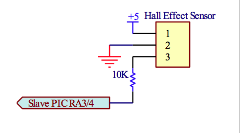
Hall Effect Sensors
|

Hall Effect Magnetic Sensor Module
This sensor was selected for its small size (easy to fit inside a pom-pom), digital read-out, relatively low price (<$2), supply voltage could be 5V, and fast shipping speed. We also purchased a similar board with a reed switch in place of the A3144E Hall Effect IC. Their performances were comparable, so we selected the Hall Effect IC over the reed switch because the latter is not as mechanically robust.
|
Coach Power Board

One 7.2V NiCd battery powered our COACH controller in combination with a 5V LDO linear regulator to maximize our run-time before the battery voltage sagged too far.
